


Вопрос как подключить однофазный электродвигатель очень часто возникает на практике из-за высокой популярности применения подобных агрегатов для решения различных бытовых задач.
Схема подключения однофазного электродвигателя достаточно проста и требует учета всего одного принципиального момента: для обеспечения его работоспособности необходимо вращающееся магнитное поле. При наличии только однофазной сети переменного тока на момент запуска электродвигателя его приходится формировать искусственно через применение соответствующих схемных решений.
Обмотки электромотора

Укладка обмоток в статоре однофазного электродвигателя
Конструкция любого однофазного электродвигателя предполагает использование как минимум трех катушек. Две из них являются элементов конструкции статора,включены параллельно. Одна из них является рабочей, а вторая выполняет функции пусковой. Их клеммы выведены на корпус двигателя и используются для подключения к сети. Обмотка ротора выполнена короткозамкнутой. К сети подключатся две из них, остальные служат для коммутации.
Для изменения мощности рабочая катушка может формироваться из двух частей, которые включаются последовательно.
Визуально идентифицировать рабочую и пусковую обмотку можно по сечению провода: у первой из них оно заметно больше. Можно замерить сопротивление тестером подключением его к клеммам: у рабочей обмотки его величина будет меньше. Как правило, сопротивления обмоток будет составлять не более нескольких десятков Ом.
Особенности формирования вращающего момента
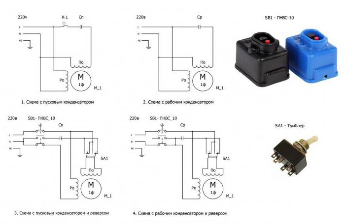
Магнитное поле, создаваемое катушками электродвигателя, имеет фазовый сдвиг на 90 градусов. Это обычно достигается через конденсатор, который последовательно включается в цепь запуска. Возможные варианты соединения показаны на рисунке ниже.

Варианты создания сдвига фаз
Пусковая катушка может работать постоянно. Допустима также схема, основанная на ее отключении после достижения номинальной частоты вращения ротора. Постоянное подключение пусковой обмотки усложняет конструкцию двигателя, но улучшает его характеристики. На особенностях подключения к сети эти различия не сказываются.
Для упрощения запуска двигателя с рабочим конденсатором, перед подачей на него тока от сети параллельно ему подключают вспомогательную емкость.
Однофазный электромотор позволяет простыми средствами изменить направление вращения вала на противоположное. Для этого производится сдвиг фазы тока, поступающего от сети и протекающего через цепи запуска, меняется на противоположный. Данная процедура реализуется простым изменением порядка включения пусковой обмотки при ее соединении с рабочей обмоткой.
Конденсаторы

Схема подключения однофазных конденсаторных двигателей: а – с рабочей емкостью Ср, б – с рабочей емкостью Ср и пусковой емкостью Сп.
Электродвигатель может комплектоваться двумя разновидностями конденсаторов. Наличие емкости, включаемой последовательно спусковой обмоткой и пропускающей через себя ток для сдвига фазы, является обязательным. Ее значение заимствуется из паспортных данных электродвигателя и дублируется на его шильдике.
При отсутствии конденсатора нужной емкости допустимо применять любой другой с близким номиналом. При слишком сильном отклонении в меньшую сторону двигатель может не начать вращаться без ручной прокрутки его вала, а затем не будет развивать нужную мощность. При значительном превышении емкости начнется сильный нагрев.
Емкость дополнительного пускового компонента выбирается в два-три раза выше по сравнению с основным. Такая величина обеспечивает максимальный стартовый момент.
Для включения пускового элемента может использоваться как обычная кнопка, так и более сложные схемы.
Косвенное включение

Подключение однофазного двигателя
Основным компонентом схемы косвенного включения является магнитный пускатель, который включается в разрыв между выходом силовой сети и электродвигателем.
Силовые контакты этого блока выполнены как нормально разомкнутые. Магнитный пускатель по величине максимального протекающего через него тока относится к одной из семи нормированных групп. Из-за небольшой мощности однофазных электродвигателей обычно достаточно устройства первой группы, максимальное значение коммутируемого тока которого составляет 10 А.
Управляющая часть катушки предназначена для подключения к сетям с различным напряжением. Наиболее удобным является магнитный пускатель с управлением от 220в переменного тока.
Особенности применения магнитного пускателя
В управляющей части устройства предусмотрено несколько пар контактов, на которых собирается схема релейной автоматики. Один из них всегда является нормально замкнутым, а второй – нормально разомкнутым.
У кнопки «Пуск» рабочим считается нормально разомкнутый контакт, а у кнопки «Стоп» задействован нормально замкнутый элемент.
При выполнении подключения рассматриваемого устройства осуществляются соединения нескольких типов.

Схема подключения однофазного двигателя
Фаза, наряду с входной клеммой, подключается также к входу контакта кнопки «Стоп», а ноль соединяется с входной клеммой катушки, что обеспечивает протекание через нее управляющего тока.
Активный контакт кнопки «Пуск» при работающем двигателе шунтируется аналогичным элементом катушки. Для формирования этой цепи выполняются два дополнительных соединения, схема которых показана на рисунке выше:
- выход рабочего контакта кнопки «Стоп» параллельно соединяется с контактами выхода кнопки «Пуск» и входа управляющей катушки,
- выход нормально разомкнутого контакта управляющей катушки параллельно соединяется с ее выходной клеммой и с входом рабочего контакта кнопки «Пуск».
Заключение
Процесс подключения однофазного электромотора к сети 220в не отличается большой сложностью и фактически требует только желания, минимального набора простейших инструментов, наличия схемы соединений и аккуратности в работе. Из расходных материалов нужны только провода. Из-за опасности короткого замыкания и больших величин токов, протекающих через обмотки двигателя, необходимо обязательно выполнять требования техники безопасности и не забывать про старое, но очень действенное правило: «Семь раз отмерь, один раз отрежь».
Благодаря индуктивности появляется электродвижущая сила и сдвиг магнитных потоков по фазе и времени. Обмотки электромотора Укладка обмоток в статоре однофазного электродвигателя Конструкция любого однофазного электродвигателя предполагает использование как минимум трех катушек.
Существуют модели, в которых пусковая обмотка работает не только при запуске, а и все остальное время. И по паре проводов выходит со статора и якоря ротора.

Именно в этом причина популярности двигателя среди населения.
Как просто подключить трехфазный двигатель треугольником и звездой в сеть 220, через конденсатор.

Крутящий момент создается за счет применения дополнительных пусковых обмоток. Вот так, шаг за шагом, мы разобрали как подключить трехфазный асинхронный электродвигатель в однофазную сеть и что для этого необходимо рассчитать и знать.
В этом случае движок гудит, ротор остается на месте. Величина конденсатора обычно указывается на табличке-шильдике двигателя и зависит от его конструктивного исполнения.
Она говорит о том, что двигатель можно подключить только через звезду. Рыженков Поделитесь этой статьей с друзьями: Вступайте в наши группы в социальных сетях:.

Пусковая и рабочие обмотки однофазных двигателей отличаются и по сечению провода и по количеству витков. Это и будет, один из сетевых проводов.

Что еще нужно для подключения? Коллекторная однофазная модель имеет в своей конструкции обмотку возбуждения и две щетки.
Подбор рабочего конденсатора для электродвигателя.
Расчет емкости конденсатора мотора
Обмотка с меньшим сечением и есть пусковая. Такие устройства имеют коэффициент мощности больший, чем у выше описанных короткозамкнутых приборов, развивают по сравнению с ними больший вращающий момент. Это можно сделать самостоятельно или воспользоваться онлайн-калькуляторами. Схема с рабочим конденсатором не предусматривает отключение дополнительной обмотки после запуска и разгона двигателя.
От однофазной сети трехфазные устройства работают с помощью емкостных или индуктивно-емкостных цепей, сдвигающих фазу.
Конденсаторы Наши читатели рекомендуют! Как подключить электродвигатель стиральной машины В современных стиральных машинах могут стоять либо коллекторные или трехфазные двигатели.

Каждая из перечисленных схем подключения подходит для использования при эксплуатации асинхронных однофазных электродвигателей в.
Функции переключателя при этом может выполнять специально предусмотренное реле.

Аксиальный паз делит каждый из них на две несимметричные половины, на меньшей из которых располагается короткозамкнутый виток.
Если для подключения асинхронного двигателя будет использована не трехфазная сеть, а бытовая однофазная то есть запитать через одну обмотку , он не заработает.
Соединение конденсаторов (часть 1)

Подключение однофазного электродвигателя: использование магнитного пускателя
Но есть другой путь — подключение однофазного электродвигателя как генератора для получения трехфазного напряжения.
В качестве кратковременного переключателя ставят кнопки с группой контактов или реле. По схеме, изображенной на рисунке 2, соединения исполнялись без нейтрали.
Функция центробежного выключателя состоит в отключении пусковой фазы, когда ротор набирает номинальную скорость. Помните, что при подключении коллекторного электрического двигателя без блока электроники, он будет работать только на максимальных оборотах, а при запуске будет сильный рывок, большой пусковой ток, искрение на коллекторе.
В конденсаторных однофазных двигателях конденсаторная обмотка работает все время. Следовательно, раз он подключается к сети , все конденсаторы, задействованные в схеме, должны быть не менее чем на В. Магнитное поле основной обмотки поддерживает вращение длительное время.

К примеру, для изготовления наждака или самодельного сверлильного аппарата. Использовать необходимо только конденсаторы, которые идут в комплекте поставки. Как рассчитать емкость Емкость конденсатора, который устанавливается в схему подключения трехфазного электродвигателя, подсоединяемого к сети напряжением в В, зависит от самой схемы. Важно помнить: трехфазные электродвигатели обладают более высокой эффективностью, чем однофазные на В.
Магнитное поле основной обмотки поддерживает вращение длительное время. Решение — установка 3-х полюсного переключателя. Данная процедура реализуется простым изменением порядка включения пусковой обмотки при ее соединении с рабочей обмоткой. Это связано с тем, что при включении в сеть только рабочей обмотки С1-С2 у однофазного конденсаторного двигателя возникнет пульсирующее магнитное поле, а не вращающееся, то есть он не запустится. С каждым из сетевых проводов необходимо подключить дроссели для исключения помех.
В магнитопроводе однофазных двигателей находится двухфазная обмотка, состоящая из основной и пусковой обмотки. Контроль показателей пускового тока в таких двигателях осуществляется частотным преобразователем. Это и будет, один из сетевых проводов. Наиболее удобным является магнитный пускатель с управлением от в переменного тока. Все емкости, которые включаются в схему, должны быть однотипными.
Если после этого двигатель окажется горячим, то: Возможно, подшипники загрязнились, зажались или просто износились. Идея применения пускового конденсатора состоит в его включении в цепь лишь в момент запуска мотора. Станках для обработки сырья и т.
Подключение конденсатора. Как подключить конденсатор к электродвигателю. Схема.
Подключение однофазного двигателя через конденсатор — 3 схемы
Что при этом получается?
Если же нагрев достаточно ощутимый, то нужно искать его причины. При значительном превышении емкости начнется сильный нагрев.
Нужно, чтобы номинальное напряжение конденсатора было равно или больше расчетного. Это оптимальное решение для достижения средних рабочих характеристик. После она выключается специальным устройством — центробежным выключателем или пускозащитным реле в холодильниках.
Во-вторых, и самое главное — автор на практике убедился, что даже предельно точный расчет не является гарантией корректной работы движка. Одна из обмоток подключается непосредственно к сети, а вторая — с использованием конденсатора. В геометрическом измерении обмотки в статоре размещаются друг напротив друга. Вот так, шаг за шагом, мы разобрали как подключить трехфазный асинхронный электродвигатель в однофазную сеть и что для этого необходимо рассчитать и знать.
См. также: Прокладка кабелей в земле нормы
Асинхронный или коллекторный: как отличить
Две из них являются элементов конструкции статора,включены параллельно. Магнитный пускатель по величине максимального протекающего через него тока относится к одной из семи нормированных групп. По сути, пусковой работает всего секунды. Как правило, сопротивления обмоток будет составлять не более нескольких десятков Ом.
К примеру, от условий эксплуатации самого двигателя, от схемы подключения, от конденсаторов, а, точнее, от их емкости. Для этого схемой предусматривается наличие специальной кнопки, предназначенной для размыкания контактов после выхода ротора на заданный уровень скорости. Еще один пример, когда замеры могут показывать 10 ом, 10 ом, 20 ом.
Когда нужно быстро раскрутить двигатель, используется схема с пусковым конденсатором. Здесь разницы нет, какой у вас будет рабочая, а какая пусковая обмотка. У однофазных асинхронных двигателей переменного тока с рабочим конденсатором вспомогательная обмотка включена постоянно через конденсатор. Но в любом случае потери будут составлять от 30 до 50 процентов.
Самые распространенные двигатели такого типа можно разделить на две группы: однофазные двигатели с пусковой обмоткой и двигатели с рабочим конденсатором. Она на втором рисунке.
Подключить трехфазный двигатель в однофазную сеть. Пусковой и рабочий конденсаторы.
Иногда встает вопрос о том, как осуществляется подключение однофазного двигателя к питающим устройствам и сетям. Однофазные асинхронные электродвигатели являются самым распространенными, поскольку их устанавливают на подавляющем большинстве различных бытовых приборов и техники (компьютерной и т.д.). Иногда такие двигатели приобретаются и устанавливаются в мастерских, гаражах и пр. для обеспечения проведения каких-либо работ (например, подъем груза).

Однофазные асинхронные электродвигатели устанавливают на подавляющем большинстве различных бытовых приборов и техники.
Работы требуют подключения однофазного электродвигателя, а это довольно сложно для человека, который не разбирается в электротехнике и электроприводе. Сложность связана с тем, что двигатель имеет много выводов, и дилетант испытывает трудности вследствие того, что не знает, какой вывод следует подключить к источнику питания. Поэтому данный материал рассматривает вопросы подключения именно для среднестатистического гражданина, который не имеет никакого представления об электроприводе и не разбирается в электротехнике.
Описание машины
Однофазными электродвижителями обычно называют асинхронные однофазные электрические машины с малой мощностью. Магнитопровод таких машин имеет двухфазную обмотку, которая делится на стартовую (пусковую) и основную. Необходимость наличия 2 обмоток заключается в следующем: они должны вызывать вращение ротора у электрического движителя (однофазного). На данный момент такие устройства условно делят на 2 категории:

Принцип работы однофазного асинхронного двигателя.
- Наличие пусковых обмоток. В этом варианте стартовая обмотка подключена через пусковой конденсатор. Когда пуск совершен, и машина развила номинальную скорость вращения, пусковая обмотка отключается от питания. После чего двигатель продолжает вращаться на подключенной к сети рабочей обмотке (конденсатор заряжается при пуске и отключает пусковую). Необходимый объем конденсатора стандартно указывает производитель машины на табличке со всеми параметрами (стандартно она должна находиться на всех двигателях).
- Машины с рабочими конденсаторами. У таких электрических машин вспомогательные обмотки всегда подключены через конденсаторы. В таком случае объем конденсаторов определяется конструкцией двигателя. При этом конденсатор остается включенным и при выходе машины на номинальный режим работы.
Чтобы правильно осуществить подключение электрической машины, необходимо уметь определить (или знать), как выведены пусковые и рабочие обмотки, а также их характеристики.
Стоит отметить: эти обмотки различны по используемым проводникам (их сечению), а также по виткам. Так для рабочих обмоток применяются проводники большего сечения, и они имеют большее количество витков. При этом важно знать, что сопротивление рабочих обмоток у разных машин всегда меньше, чем сопротивление пусковых/вспомогательных. При этом измерить сопротивление обмотки двигателя не составляет особого труда, особенно если применяются специальные мультиметры.
На основании описанного стоит привести некоторые примеры.
Примеры подключения

Схема подключения однофазного двигателя с тяжелым пуском.
Здесь рассмотрим 3 варианта движителей, которые отличаются друг от друга.
Вариант №1. У движителя имеется 4 вывода. Сначала находят концы обмоток (обычно они располагаются попарно, поэтому увидеть их не составляет труда).
Вариантов расположения выводов может быть 2: либо все 4 в один ряд, либо 2 в одном ряду и 2 во втором. В первом случае определить обмотки проще: первая пара – одна обмотка, вторая – другая.
Во втором случае можно запутаться между обмотками. Наиболее часто распространен вариант, когда один вертикальный ряд – одна обмотка, другой – вторая. Но стоит знать, что мультиметр выдаст значение бесконечного сопротивления, если выбраны выводы разных обмоток. А далее все просто.
Определяют сопротивление у обмоток: там, где меньшее сопротивление, – та рабочая, а большее – пусковая.
Подключение осуществляется следующим образом: на толстые провода подают 220 В, а один вывод пусковой соединяют с выводом рабочей. При этом не стоит беспокоится о правильности соединения выводов – работа машины и то, в какую сторону осуществляется вращение, не изменятся от того, какой конец с каким был соединен. Направление вращения изменяется из-за смены концов подключения стартовой обмотки.

Схема подключения однофазного двигателя в прямом направлении.
Второй вариант – когда у машины имеется 3 вывода. В этом случае при измерении сопротивлений между обмотками мультиметр будет показывать различные значения – минимальное, максимальное, среднее (если их мерять попарно). Здесь общий конец, который будет у минимального и среднего значения, является одним из концов подключения, другой вывод для подключения сети – тот, который имеет минимальное значение. Вывод, который останется, – вывод пусковой обмотки – должен быть подключен с конденсатором и с одним из концов подачи питания сети. В этом случае невозможно самостоятельно изменить направление вращения.
Последний пример. Есть 3 вывода, а замеры сопротивления между выводами попарно показали, что имеется 2 абсолютно одинаковых значения и одно большее (примерно в 2 раза). Такие движители часто ставились на старые и устанавливаются на современные стиральные машины. Это именно тот случай, когда обмотки у машины идентичны, поэтому абсолютно без разницы, как подключать обмотки.
Как это применить на практике? Это самый часто задаваемый вопрос, ведь с подключением инструментов (болгарок, перфораторов, шуруповертов и т.д.) могут возникнуть сложности. Это иногда связано с тем, что в инструменте используется коллекторный движитель, который зачастую работает без пусковых приспособлений. Рассмотрим этот вариант подробнее.
Пуск электродвигателя с коллектором

Схема подключения однофазного двигателя в обратном направлении.
Этот случай самый распространенный. В главе выше он обозначен под примером №3. Такие двигатели часто применяются для бытовых устройств, ведь они просты и дешевы.
Обычно концы у таких двигателей нумеруются. Поэтому для подключения следует соединить выводы 2 и 3 друг с другом (один идет от якоря, а другой от статора), а номера 1 и 2 подключить к источнику питания.
Следует знать, что если подключить такую машину без специальных электронных устройств, то она будет выдавать только максимальное количество оборотов и регулировка скорости будет невозможна. При этом будет большой пусковой ток и рывковое усилие при пуске.
Если требуется изменение направления вращения движителя, то следует изменить местами подключение выводов статора либо якоря.
Практическое подключение
Если есть двигатель, который следует подключить к сети, то требуется внимательно изучить его табличку, где приведены номинальные значения машины и конденсатора (или нескольких конденсаторов). Далее по наименованию модели электрической машины рекомендуется найти схему.

Схемы подключения однофазного электродвигателя.
Схема подключения однофазного электродвигателя для разных устройств может быть различна, поэтому рекомендуется подобрать схему для конкретного варианта. В противном случае могут возникнуть проблемы, вплоть до полного выхода из строя движителя (когда он сгорит). Далее следует подобрать конденсатор (если он вышел из строя или его нет). Подбор осуществляется по специальным таблицам, которые есть в справочной литературе.
Рассмотрим в качестве примера стиральную машину последних годов выпуска. Там обычно применяется коллекторный или трехфазный движитель. В случае наличия трехфазного движителя осуществить его пуск можно только подключением специального пускового блока, который необходимо подобрать под конкретную модель стиральной машины.
В случае наличия коллекторной машины на клеммник будут выведены около 7 проводов (±1) без учета вывода заземления (он маркируется соответствующим знаком, и к нему подходит желто-зеленый провод). Пара выводов обычно имеет тахометр, они не подключаются к сети. И по 2 выхода имеют статор и ротор электрической машины и маркировку буквенно-цифирную (например, А1-а1, или А-а). Первая буква (заглавная) обозначает начало обмотки, вторая – конец. Другая обмотка обозначается следующей буквой латинского алфавита. Питание подается на начало роторной и конец статорной обмотки. Для этого необходимо заранее определиться с обмоткой (какая откуда). После чего свободные выводы обмоток соединяются при помощи перемычки.
После этого следует осуществить пробный пуск устройства, причем соблюдая правила техники безопасности.
После своего изобретения трехфазные двигатели успешно используются до сих пор без каких-либо существенных изменений. Подключение асинхронного двигателя к однофазной сети было лишь делом времени, так как они намного проще в эксплуатации и обслуживании, чем их коллекторные собратья. А ведь в домашних условиях используется именно однофазная сеть, а хороший двигатель нужен не только на производстве. Какие электрические машины можно использовать дома или на даче, и как правильно их запустить в работу от обычных 220 В?
Одна фаза вместо трех
 Самый распространенный вариант – трехфазный асинхронный двигатель. В пазах неподвижного статора уложены три обмотки со сдвигом 120 электрических градусов. Для пуска необходимо через них пропустить трехфазный ток, который, проходя по каждой обмотке в разное время, создает вращающий момент, раскручивающий ротор. При подключении однофазной сети такого не происходит. Поэтому здесь необходимы дополнительные элементы, такие как фазосдвигающий конденсатор. Это самый простой способ.
На скорость вращения ротора это не повлияет, а вот мощность такой электрической машины упадет. В зависимости от нагрузки на валу, емкости конденсатора, схемы подключения, потери составляют 30–50 %.
Стоит сразу отметить, что аппараты не всех марок работают по однофазной схеме. Но все-таки большинство позволяет проводить с собой подобные манипуляции. Всегда стоит обращать внимание на прикрепленные таблички. Там есть все характеристики, глядя на которые можно увидеть, какая это модель и где она будет работать.
 Из первой картинки (А) можно сделать вывод, что данный двигатель рассчитан на два напряжения – 220 и 380 В. Включение обмоток – треугольник и звезда. От обычной домашней сети его запустить можно (есть соответствующее напряжение), и желательно треугольником.
Вторая (Б) показывает: электрическая машина рассчитана на 380 В, включение звездой. Теоретически, на меньшее напряжение переключиться возможно, но для этого нужно разбирать корпус, искать соединение обмоток и переключать их на треугольник. Можно, конечно, ничего не переключать просто поставив конденсатор. Однако потери мощности будут колоссальными.
Если на табличке написано: Δ/Ỵ 127/220, то к сети 220 В такой аппарат можно включать только звездой, иначе он сгорит!
Подключение фазосдвигающего конденсатора
Оптимальный вариант подключения трехфазной машины в работу от 220 вольт, это треугольником. Так потери составят около 30%. Два конца в борне идут непосредственно к сети, а между третьим концом и любым из этих двух включают конденсатор.

Такой пуск возможен если нет никакой серьезной нагрузки: например, при подключении вентилятора. Если будет нагрузка, то ротор либо не будет крутиться вообще, либо запуск будет происходить очень долго. В этом случае стоит добавить пусковой конденсатор.

При этом будет хорошо использовать выключатель, у которого один контакт замыкался бы и фиксировался, пока его не отключишь, а другой отключался, когда его отпускают. Так можно на непродолжительное время подсоединять в работу пусковой конденсатор. Направление вращения изменяется переключением конденсатора в схеме на другую фазу.
На практике это может выглядеть так:

Схема для пуска в работу трехфазного двигателя к однофазной цепи звездой тоже несложная. Потери будут больше, но иногда другого выхода просто нет.

Расчет конденсатора
Вполне естественный вопрос о том, конденсатор с какими параметрами нужно использовать для запуска и работы такого аппарата. Все зависит от того, звездой или треугольником соединены обмотки на трехфазной машине.
- Для звезды существует такой расчет: Cр = 2800•I/U.
- Треугольник:Cр = 4800•I/U.
Cр– емкость рабочего конденсатора в микрофарадах, I – ток в амперах, U – напряжение сети в вольтах.
- Ток можно посчитать таким образом: I = P/(1.73•U•n•cos ф).
Р – это мощность асинхронного аппарата, написанная на его бирке,n – его КПД. Он указан там же, рядом написан и cos ф.
Есть и упрощенный вариант расчета. Он выглядит таким образом: C = 70•Pн, где Pн – это номинальная мощность, кВт (на бирке). Из этой формулы можно сделать вывод, что на каждые 100 Вт должно быть около 7 мкФ емкости.
При завышенной емкости конденсатора обмотки будут сильно греться, при заниженной ротор будет тяжело раскручиваться. Поэтому идеальным вариантом является, когда после всех расчетов делается своеобразная «подгонка»: замеряется ток при помощи клещей и добавляются или убираются дополнительные конденсаторы.
Если нужен пусковой конденсатор, то необходимо подобрать его так, чтобы общая емкость (Ср+Сп) в 2–3 раза превышала рабочую(Ср).
Постепенный разгон
Как можно осуществить плавный пуск асинхронного двигателя в однофазной сети? Стоит сразу оговориться, что для домашнего использования это обойдется дорого. Сама схема очень сложна и пробовать собрать ее самостоятельно не имеет смысла. Существуют специальные устройства плавного пуска, которые успешно используются для этой цели. Суть их заключается в том, что первые секунды включения напряжение питания подается заниженным, вследствие чего занижен пусковой момент.
Но так как частота вращения роторатаких аппаратов зависит от частоты питающего напряжения, а не от его величины, то такой вариант подходит только тогда, когда нет значительной нагрузки на валу: насосы, вентиляторы. Если есть нагрузка, тогда лучше всего использовать частотный преобразователь. Он также обеспечит плавный запуск, а также много других замечательных возможностей. Правда, стоит он дороже. Из этого следует вывод: такие устройства больше подходят для использования на производстве, пусть даже небольшом. Для дома это дорого.

Как видно, этот частотник можно питать как трехфазным напряжением, так и одной фазой.
Одна фаза
Для того чтобы выполнить подключение однофазного асинхронного двигателя, достаточно двух кнопок: одна с фиксатором, другая без него. Стандартная схема: две обмотки, включенные последовательно (хотя, в зависимости от модели, могут быть варианты). Та, у которой большее сопротивление – пусковая, другая – рабочая.

Каждая модель электрической машины имеет свои характеристики, а значит, и варианты подключения могут различаться. У некоторых для запуска используется два конденсатора, у других – один.

Следовательно, начинать необходимо с выяснения модели и ее технических характеристик.
Как видно, запуск короткозамкнутых электрических машин возможен по-разному. Подключение возможно как в домашних условиях, так и на производстве, что сделало их такими популярными. И, по большому счету, более чем за сто лет не было придумано ничего лучше.
90000 Single-phase induction motor 90001 90002 By Dmitry Levkin 90003 A 90004 single-phase induction electric motor 90005 is an induction electric motor that operates from a single-phase AC power grid without using a frequency converter and which, in the basic mode of operation (after starting), uses only one winding (phase) of the stator. 90002 90004 Split-phase motor 90005 is a single-phase induction motor having an auxiliary (starting) winding on the stator, offset from the main one, and a squirrel-cage rotor [2].90003 90010 Construction of Single-phase Induction Motor with auxillary or starting winding 90011 The main components of any electric motor are the rotor and the stator. The rotor is the rotating part of the electric motor, the stator is the fixed part of the electric motor, with the help of which a magnetic field is created for the rotation of the rotor. 90002 The main parts of a single-phase induction motor: rotor and stator 90003 90002 The 90015 stator 90005 has two windings located at an angle of 90 ° relative to each other.The main (working) winding usually occupies 2/3 of the slots of the stator core, the other winding is called auxiliary (starting) and usually takes 1/3 of the slots of the stator. 90003 90002 The motor is actually two-phase, but since only one winding is working after starting, the electric motor is called single-phase. 90003 90002 The 90021 rotor 90005 usually represents itself a short-circuited winding, also called «squirrel cage» due to the similarity. Whose copper or aluminum rods are closed with rings at the ends, and the space between the rods is often filled with an aluminum alloy.The rotor of a single-phase motor can also be made in the form of a hollow nonmagnetic or hollow ferromagnetic cylinder. 90003 90002 Single-phase induction motor with auxiliary winding has two windings located perpendicularly relative to each other 90003 90010 Working principle of single-phase induction motor 90011 90002 To better understand the working of a single-phase induction motor, let’s consider it with only one turn in the main and auxiliary windings. 90003 90002 Analysis of the case with two windings having one turn 90003 90002 Consider the case when no current flows in the auxiliary winding.When the main stator winding is turned on, the alternating current, passing through the winding, creates a pulsating magnetic field, stationary in space, but varying from + Ф 90033 max 90034 to-Ф 90033 max 90034. 90003 90002 Start 90003 90002 Stop 90003 90002 Fluctuating magnetic field 90003 90002 If you place a squirrel-cage rotor having an initial rotation in a fluctuating magnetic field, it will continue to rotate in the same direction.90003 90002 To understand the working principle of a single-phase induction motor, we separate the fluctuating magnetic field into two identical rotating fields having an amplitude equal to Ф 90033 max 90034/2 and rotating in opposite directions with the same frequency: 90003 90002, 90003 90052 90053 where n 90033 90055 f 90056 90034 is the rotational speed of the magnetic field in the forward direction, rpm, 90058 90053 n 90033 90055 r 90056 90034 is the rotational speed of the magnetic field in the opposite direction, rpm, 90058 90053 f 90033 1 90034 is stator current frequency, Hz, 90058 90053 p is a number of poles pairs, 90058 90053 n 90033 1 90034 is the rotational speed of magnetic flux, rpm 90058 90075 90002 Start 90003 90002 Stop 90003 90002 The decomposition of the fluctuating magnetic flux into two rotating 90003 90082 The action of the fluctuating field on a rotating rotor 90083 90002 Consider the case when the rotor in a fluctuating magnetic flux has an initial rotation.For example, we manually spun the shaft of a single-phase motor, one winding of which is connected to an AC power grid. In this case, under certain conditions, the motor will continue to develop torque, since the rotor 90004 slip 90005 relative to the forward and reverse magnetic flux will be unequal. 90003 90002 Assume that the forward magnetic flux Ф 90033 f 90034, rotates in the direction of rotor rotation, and the reverse magnetic flux Ф 90033 r 90034 in the opposite direction. Since, the rotational speed of the rotor n 90033 2 90034 is less than the rotational speed of the magnetic flux n 90033 1 90034, the slip of the rotor relative to the flux Ф 90033 f 90034 will be: 90003 90002, 90003 90052 90053 where s 90033 90055 f 90056 90034 is rotor slip relative to the forward magnetic flux, 90058 90053 n 90033 2 90034 is rotor speed, rpm, 90058 90053 s is induction motor slip 90058 90075 90002 Forward and reverse rotating magnetic flux instead of fluctuating magnetic flux 90003 90002 The magnetic flux Ф 90033 r 90034 rotates counter to the rotor rotation, the rotor rotation speed n 90033 2 90034 relative to this flux is negative, and the slip of the rotor relative to Ф 90033 r 90034 90003 90002, 90003 90052 90053 where s 90033 90055 r 90056 90034 is rotor slip relative to reverse magnetic flux 90058 90075 90002 Start 90003 90002 Stop 90003 90002 Rotating magnetic field penetrating the rotor 90003 90002 Current induced in the rotor by an alternating magnetic field 90003 90002 According to the law of electromagnetic induction, the forward Ф 90033 f 90034 and reverse Ф 90033 r 90034 magnetic fluxes generated by the stator winding induce EMF in the rotor winding, which, respectively, in the short-circuited rotor generate currents I 90033 2f 90034 and I 90033 2r 90034.The frequency of the current in the rotor is proportional to the slip, therefore: 90003 90002, 90003 90052 90053 where f 90033 2f 90034 is frequency of the current I 90033 2f 90034 induced by the forward magnetic flux, Hz 90058 90075 90002, 90003 90052 90053 where f 90033 2r 90034 is frequency of the current I 90033 2r 90034 induced by the reverse magnetic flux, Hz 90058 90075 90002 Thus, when the rotor rotates, the electric current I 90033 2r 90034 induced by the reverse magnetic field in the rotor winding has a frequency f 90033 2r 90034 much higher than the frequency f 90033 2f 90034 of the rotor current I 90033 2f 90034 induced by the forward field.90003 90004 Example: 90005 for a single-phase induction motor working from the mains with a frequency f 90033 1 90034 = 50 Hz at n 90033 1 90034 = 1500 and n 90033 2 90034 = 1440 rpm, 90002 slip of the rotor relative to the forward magnetic flux s 90033 f 90034 = 0.04; 90195 the frequency of the current induced by the forward magnetic flux f 90033 2f 90034 = 2 Hz; 90195 slip of the rotor relative to the reverse magnetic flux а s 90033 r 90034 = 1,96; 90195 the frequency of the current induced by the reverse magnetic flux f 90033 2r 90034 = 98 Hz 90003 90002 According to Ampere’s law, a torque occurs as a result of the interaction of the electric current I 90033 2f 90034 with the magnetic field F 90033 f 90034 90003 90002, 90003 90052 90053 where M 90033 90055 f 90056 90034 is the magnetic torque created by the forward magnetic flux, N ∙ m, 90058 90053 з 90033 90055 M 90056 90034 is constant coefficient determined by the motor construction 90058 90075 90002 The electric current I 90033 2r 90034, interacting with the magnetic field Ф 90033 r 90034, creates a braking torque M 90033 r 90034 directed against the rotation of the rotor, that is, opposite to the torque M 90033 f 90034: 90003 90002, 90003 90052 90053 where M 90033 r 90034 is magnetic torque created by reverse magnetic flux, N ∙ m 90058 90075 90002 The resulting torque acting on the rotor of a single-phase induction motor, 90003 90002, 90003 90002 90004 Note: 90005 Due to the fact that in a rotating rotor forward and reverse magnetic field will induce a current of different frequency, the torques acting on the rotor in different directions will not be equal.Therefore, the rotor will continue to rotate in a fluctuating magnetic field in the direction in which it had an initial rotation. 90003 90082 The braking effect of the reverse field 90083 90002 When a single-phase motor is operating within the rated load, that is, at small slip values s = s 90033 f 90034, the torque is generated mainly due to the torque M 90033 f 90034. The braking effect of the torque of the reverse field M 90033 r 90034 slightly. This is due to the fact that the frequency f 90033 2r 90034 is much higher than the frequency f 90033 2f 90034, therefore, the inductive reactance of the rotor winding а х 90033 2r 90034 = x 90033 2 90034 s 90033 r 90034 to the current I 90033 2r 90034 is much more than its active resistance.Therefore, the current I 90033 2r 90034 having a large inductive component has a strong demagnetizing effect on the reverse magnetic flux Ф 90033 r 90034, significantly weakening it. 90003 90002, 90003 90052 90053 where r 90033 2 90034 is rotor rods resistance, Ohm, 90058 90053 x 90033 2r 90034 is reactive impedance of rotor rods, Ohm. 90058 90075 90002 If we consider that the power factor is small, then it will become clear why the M 90033 r 90034 under the load of the motor does not have a significant braking effect on the rotor of a single-phase motor.90003 90002 With one phase, the rotor can not be started. 90003 90002 The rotor having the initial rotation will continue to rotate in the field created by the single-phase stator 90003 90082 The action of a fluctuating field on a fixed rotor 90083 90002 With a stationary rotor (n 90033 2 90034 = 0) slip s 90033 f 90034 = s 90033 r 90034 = 1 and M 90033 f 90034 = M 90033 r 90034, therefore the initial starting torque of a single-phase induction motor M 90033 f 90034 = 0.To create the starting torque, it is necessary to bring the rotor in rotation in one direction or another. Then s ≠ 1, the equality of the torques М 90033 f 90034 and М 90033 r 90034 is violated and the resulting electromagnetic torque acquires some value M = M 90033 90055 f 90056 90034 — M 90033 90055 r 90056 90034 ≠ 0. 90003 90010 Starting of a single-phase induction motor. How to create an initial rotation? 90011 90002 One way to create a starting torque in a single-phase induction motor is to position the auxiliary (start) winding B, which is offset in space relative to the main (run) winding A at an angle of 90 electrical degrees.In order that the stator windings to create a rotating magnetic field, the currents I 90033 A 90034 and I 90033 B 90034 in the windings must be out of phase relative to each other. To obtain a phase shift between the currents I 90033 A 90034 and I 90033 B 90034, the auxiliary (start) winding B is connected to a phase-shifting element, which is resistance (resistor), inductance (choke) or capacitance (capacitor) [1]. 90003 90002 After the motor rotor accelerates to a rotational speed close to steady, the starting winding B is disconnected.The auxiliary winding is disconnected either automatically using a centrifugal switch, a time delay relay, a current or a differential relay, or manually using a button. 90003 90002 Thus, during start-up, the single-phase induction motor operates as two-phase, and after the start-up, as single-phase. 90003 90010 Single-phase induction motor connection 90011 90082 Resistance start induction motor 90083 90002 90004 Resistance start 90005 induction motor is a split-phase motor, in which the auxiliary winding circuit is distinguished by increased resistance.90003 90002 Ohmic phase shift, bifilar starting winding 90003 90002 Different resistance and inductance of the windings 90003 90002 To start a single-phase induction motor, you can use a starting resistor, which is connected in series to the starting winding. In this case, it is possible to achieve a phase shift of 30 ° between the currents of the main and auxiliary windings, which is quite enough to start the motor.In a motor with starting resistance, the phase difference is explained by the different complex impedance of the circuits. 90003 90002 Also, a phase shift can be created by using a start winding with a lower inductance and higher resistance. For this, the starting winding is done with a smaller number of turns and using a thinner wire than in the main winding. 90003 90082 Capacitor start induction motor 90083 90002 90004 Capacitor start 90005 induction motor is a split-phase motor, in which the auxiliary winding circuit with a capacitor is switched on only for the duration of the start.90003 90002 Capacitive phase shift with a starting capacitor 90003 90002 To achieve the maximum starting torque, it is required to create a circular rotating magnetic field, this requires that the currents in the main and auxiliary windings are shifted relative to each other by 90 °. The use of a resistor or choke as a phase-shifting element does not allow for the required phase shift. Only the inclusion of a capacitor of a certain capacity allows for a phase shift of 90 °.90003 90002 Among phase shifting elements, only a capacitor allows achieving the best starting properties of a single-phase induction electric motor. 90003 90002 Motors in the circuit of which a permanently switched on capacitor use two phases for operation and are called capacitor ones. The working principle of these motors is based on the use of a rotating magnetic field. 90003 90002 90004 Shaded pole induction motor 90005 is a split-phase motor in which the auxiliary winding is short-circuited.90003 90002 The 90004 stator 90005 of a shaded pole single-phase induction motor usually has salient poles. Each stator pole is divided into two unequal sections by an axial groove. A smaller section of the pole has a short-circuited turn. The 90004 rotor 90005 of a shaded pole single-phase motor is short-circuited in the form of a squirrel cage. 90003 90002 When the single-phase stator winding is turned on to the power grid, a fluctuating magnetic flux is created in the motor magnetic circuit.One part of which passes through unshaded Ф ‘, and the other Ф «along the shaded section of the pole. Flow Ф» induces EMF E 90033 k 90034 in a short-circuited turn, resulting in a current I 90033 k 90034 lagging from E 90033 k 90034 in phase due to the inductance of the coil. The current I 90033 k 90034 creates a magnetic flux Ф 90033 k 90034, directed oppositely to Ф «, creating the resulting flux in the shaded section of the pole Ф 90033 s 90034 = Ф» + Ф 90033 k 90034. Thus, in a motor, the flows of the shaded and unshaded sections of the pole are shifted in time by a certain angle.90003 90002 The spatial and temporal shear angles between the flows Ф 90033 s 90034 and Ф ‘create conditions for a rotating elliptical magnetic field to appear in the motor, since Ф 90033 s 90034 ≠ Ф’. 90003 90002 Starting and working properties of the considered motor are low. Efficiency is much lower than that of capacitor start induction motors of the same power, which is associated with significant electrical losses in a short-circuited coil. 90003 90002 The 90004 stator 90005 of such a single-phase motor is made with salient poles on a non-symmetrical laminated core.The 90004 rotor 90005 has squirrel-cage winding. 90003 90002 This motor for an operation does not require the use of phase-shifting elements. The disadvantage of this motor is low efficiency. 90003 90415 Also read 90416 .90000 Single Phase Induction Motor — Working Principle and Construction 90001 90002 Single-phase motors are the most familiar of all-electric motors because they are extensively used in home appliances, shops, offices etc. 90003 90002 It is true that single-phase motors are a less efficient substitute for 3-phase motors but 3-phase power is normally not available except in large commercial and industrial establishments. 90003 90006 Working of Single Phase Induction motor 90007 90002 Unlike three-phase induction motors, single-phase induction motors are not self-starting.The reason behind this is very interesting. 90003 90010 Why Single Phase Induction Motor is Not Self Starting? 90011 90002 The single-phase induction motor has 90013 90014 distributed stator winding 90015 90016 and a 90013 90014 squirrel-cage rotor 90015 90016. 90003 90022 When fed from a single-phase supply, its stator winding produces a flux (or field) which is only alternating i.e. one which alternates along one space axis only. 90003 90022 It is not synchronously revolving (or rotating) flux as in the case of a two or a three-phase stator winding fed from a 2 of 3 phase supply.90003 90022 Now, an alternating or pulsating flux acting on a stationary squirrel-cage rotor can not produce rotation (only a revolving flux can produce rotation). 90027 That is why a single phase motor is not self-starting. 90028 90003 90022 However, if the rotor of such a machine is given an 90013 90014 initial start 90015 90016 90013 by hand 90016 (or small motor) or otherwise in either direction, then immediately a torque arises and the motor accelerates to its final speed ( unless the applied torque is too high).90003 90022 This peculiar behavior of the motor has been explained using two theories below 90003 90040 90041 Two-field or 90027 double-field revolving theory 90028 90044 90041 90027 Cross-field theory 90028. 90044 90049 90002 Only the double field revolving theory will be discussed briefly. 90003 90002 90010 Double Field Revolving Theory 90011 90003 90002 This theory makes use of the idea that an alternating uniaxial quantity can be represented by two oppositely rotating vectors of half magnitude.90003 90002 So, an alternating sinusoidal flux can be represented by two revolving fluxes, each equal to half the value of alternating flux and each rotating synchronously in opposite directions. 90003 90060 90060 Double Field Revolving Theory 90002 As shown in Fig. (A), let the alternating flux have a maximum value of φ 90063 m 90064. It’s component fluxes A and B will each be equal to 90013 φ 90063 m 90064/2 90016 revolving in anticlockwise and clockwise directions respectively. 90003 90002 After some time when A and B would have rotated through the angles + θ and -θ as in Fig (b), the resultant flux would be 90003 90002 90013 Resultant Flux = 2 × (φ 90063 m 90064/2) sin ( 2θ / 2) = φ 90063 m 90064 sin θ 90016 90003 90002 After a quarter cycle of rotation, fluxes A and B will be oppositely directed as shown in Fig (c) so that the resultant flux would be zero.90003 90002 After half a cycle, fluxes A and B will have a resultant of 90013 -2 × (φ 90063 m 90064/2) = -φ 90063 m 90064. 90016 90003 90002 After three-quarters of a cycle, again the resultant is zero as shown in Fig (e) and so on. 90003 90002 If we plot the values of resultant flux against θ between limits θ = 0 ° to θ = 360 °, then a curve similar to the one shown in the figure is obtained. 90003 90094 90094 Alternating Flux 90002 That is why an alternating flux can be looked upon as composed of two revolving fluxes each of half the value and revolving synchronously in opposite directions.90003 90002 It may be noted that if the slip of the rotor is 90014 s 90015 with respect to the forward rotating flux (ie one which rotates in the same direction as the rotor) then its slip with respect to backward rotating flux is (2 s). 90003 90102 90102 Torque vs Slip 90002 Each of the two-component fluxes while revolving around the stator cuts the rotor, induces an emf, and thus produces its own torque. 90003 90002 Obviously, the two torques (called forward and backward torques) are oppositely-directed so that the net or resultant torque is equal to their difference.90003 90002 Hence, T 90063 f 90064 and T 90063 b 90064 are numerically equal but being oppositely directed, produce no resultant torque. 90027 That explains why there is no starting torque in a single-phase motor 90028. 90003 90002 However, if the rotor is started somehow, say, in the clockwise direction, the clockwise torque starts increasing and, at the same time, the anticlockwise torque starts decreasing. 90003 90002 Hence, there is a certain amount of net torque in the clockwise direction which accelerates the motor to full speed.90003 90010 How to Make Single Phase Induction Motor Self Starting? 90011 90002 As discussed above, single phase induction motors are not self-starting because a single phase supply can not produce a rotating magnetic field. We require a two phase or three phase supply for the production of rotating magnetic field. 90003 90002 90013 But we can create a rotating magnetic field by a two-phase construction. 90016 90003 90002 So simply we can say in order to make a single phase induction motor self-starting, we have to temporarily convert it into a two-phase motor during its starting period.90003 90002 For this purpose, the stator of the single-phase induction motor is provided with an extra winding known as 90013 Starting or Auxillary Winding 90016 in addition to the 90013 Main or Running Winding 90016. 90003 90002 The two winding are 90 degrees electrically displaced and are connected in parallel across the single phase supply. 90003 90002 It is so arranged that the phase difference between the currents in two stator windings (main and running windings) is very large (ideal value is 90 degree).Hence the motor behaves like a 90013 two-phase motor. 90016 90003 90002 These two currents produce a revolving flux and hence make the motor self-starting. 90003 90002 The phase difference between the currents in the main winding and running winding can be obtained through different methods. The phase shift can be achieved by connecting a resistance, inductance or capacitance in series with the starting winding. 90003 90010 How Phase Shift is Created? 90011 90002 The difference between the current in starting winding and running winding in different single phase motors are created by different methods.90003 90002 In this section, we will look into how the phase shift is created in each single phase motors. 90003 90152 Split Phase Induction Motor 90153 90002 In a split-phase induction motor the phase difference created by using windings of different resistance and reactance in the main winding and auxiliary winding. 90003 90002 Main winding (Running Winding): Low Resistance but High Reactance 90003 90002 Auxiliary Winding (Starting Winding): High Resistance and Low Reactance 90003 90152 Capacitor Start Induction Motors 90153 90002 Capacitor Start induction motors use a capacitor in series with the auxiliary winding to create a phase difference between the main winding and auxiliary winding.90003 90002 Generally, an electrolytic type of capacitor is used for this function. 90003.90000 Three Ways to Control a Single-Phase Induction Motor 90001 90002 Every day engineers design products that employ single-phase induction motors. Speed control of single-phase induction motors is desirable in most motor control applications since it not only provides variable speed but also reduces energy consumption and audible noise. 90003 90002 Most single-phase induction motors are unidirectional, which means they are designed to rotate in one direction.Either by adding extra windings, external relays and switches, or by adding gear mechanisms, the direction of rotation can be changed. Using microcontroller-based control systems, one can add speed variation to the system. In addition to the option of speed variation, the direction of rotation can also be changed, depending upon the motor control algorithms used. 90003 90002 Permanent Split Capacitor (PSC) motors are the most popular type of single-phase induction motors. This article will discuss different techniques and drive topologies to control the speed of a PSC motor in one and two directions.90003 90008 Microcontroller Interface 90009 90002 A microcontroller is the brain of the system. Often, the controllers used for motor control applications have specialized peripherals like motor-control PWMs, high-speed analog-to-digital converters (ADCs), and diagnostic pins. The PIC18F2431 and dsPIC30F2010 from Microchip both have these features built in. 90003 90002 Having access to the microcontroller’s specialized, on-chip peripherals makes the implementation of control algorithms easier.90003 90002 ADC channels are used to measure motor current, motor temperature and heat sink temperature (connected to the power switches). A third ADC channel is used to read potentiometer levels, which is then used to set the speed of the motor. Additional ADC channels can be used in the final application to read different sensors, such as the proximity switch, turbidity sensors, water level, freezer temperature, etc. 90003 90002 General-purpose inputs and outputs (I / Os) can be used for interfacing switches and displays in an application.For example, in a refrigerator application, these general-purpose I / Os can be used to control an LCD display, seven-segment LED display, push-button interface, etc. Communication channels like I2C 90017 (TM) 90018 or SPI 90017 (TM) 90018 are used to connect the motor control board with another board to exchange data. 90003 90002 Fault and diagnostics interfaces include input lines with special features like the ability to shut down the PWMs in case of catastrophic faults in the system. For example, in a dish-washer, if the drive is blocked due to accumulated waste, it could prevent the motor from rotating.This blockage can be detected in the form of over current in the motor control system. Using the diagnostics features, these types of faults can be logged and / or displayed, or transferred to the trouble-shooting PC of a service person. Often, this will prevent hard failures and reduce the downtime of the product, resulting in reduced service costs. 90003 90024 90025 90026 90027 90028 90029 90026 90027 90032 The hardware interface for the PIC 18F2431 or dsPIC30F2010.90033 90028 90029 90036 90037 90002 PWMs are the main peripherals used to control the motor. Using the above inputs, the microcontroller’s motor control algorithm determines the PWM duty cycle and pattern of output. The PWM’s most valuable features include complementary channels with programmable dead time. PWMs can be edge-aligned or center-aligned. Center-aligned PWMs have the advantage of reduced electromagnetic noise (EMI) being emitted by the product. 90003 90008 Option # 1: Unidirectional Control 90009 90002 VF control in one direction makes the drive topology and control algorithm relatively easy.The task is to generate a variable voltage and frequency power supply from a fixed voltage and frequency power supply (such as a wall-outlet power supply). The figure on page 85 shows the block diagram representation of this drive topology, with the three basic building sections discussed earlier. Motor windings are connected to the center of each half bridge on the output-inverter section. Many motors available off the shelf have both the main and start windings connected together with a capacitor connected in series with the start winding.With this configuration, the motor may have only two protruding wires (M1 and M2). 90003 90002 The MCU shown in the block diagram has a Power Control PWM (PCPWM) module, which is capable of outputting up to three pairs of PWMs with deadband in between the pairs. Deadband is essential in an induction motor control application to avoid cross conduction of the dc bus through the power switches when one turns OFF and the other turns ON. The diagnostic circuit may include motor current monitoring, dc-bus voltage monitoring, and temperature monitoring on the heat sink connected to the power switches and the motor.90003 90024 90025 90026 90027 90028 90029 90026 90027 90032 Block diagram representation of the drive topology with the three basic building sections. With this configuration, the motor may have only two protruding wires (M1 and M2). The MCU shown has a PWM module that is capable of outputting up to three pairs of PWMs with deadband between the pairs. 90033 90028 90029 90026 90027 90028 90029 90026 90027 90032 Bidirectional control using an H-bridge.90033 90028 90029 90036 90037 90008 Bidirectional Control 90009 90002 Most PSC motors are designed to run in one direction. However, many applications call for bidirectional motor rotation. Historically, gear mechanisms or external relays and switches were used to achieve bidirectional rotation. When mechanical gears are used, the motor shaft runs in one direction, and the gears for forward and reverse engage and disengage according to the direction required. Using relays and switches, the polarity of the starting winding is electrically reversed based on the direction required.90003 90002 Unfortunately, all of these components increase the cost of the system for basic ON and OFF control in two directions. 90003 90002 In this section, we will discuss two methods of bidirectional speed control for PSC motors using a microcontroller-based drive. The drive topologies discussed here produce effective voltages, which drive the main winding and start winding at 90-degree phase shifts to each other. This enables the system designer to remove the capacitor, which is in series with start winding, from the circuit permanently-thereby reducing the total system cost.90003 90008 Option # 2: H-Bridge Inverter 90009 90002 This method has a voltage doubler on the input side; on the output side an H-bridge or two-phase inverter is used (see figure above). One end of the main and start windings are connected to each half bridge; the other ends are connected together at the neutral point of the ac power supply, which also serves as the center point for the voltage doubler. 90003 90002 The control circuit requires four PWMs with two complementary pairs and sufficient deadband between the complementary outputs.PWM0-PWM1 and PWM2-PWM3 are the PWM pairs with dead band. Using PWMs, the dc bus is synthesized to provide two sine voltages at 90 degrees out of phase with varying amplitude and varying frequency, according to the VF profile. If the voltage applied to the main winding lags the start winding by 90 degrees, then the motor runs in the forward direction. To reverse the direction of rotation, the voltage supplied to the main winding should lead the voltage supplied to the start winding. 90003 90024 90025 90026 90027 90028 90029 90026 90027 90032 Phase voltages when the motor is running in forward and reverse direction.90033 90028 90029 90036 90037 90002 This H-bridge inverter method of controlling a PSC type motor has following disadvantages. 90003 90002 The main and start windings have different electrical characteristics. Thus, the current flowing through each switch is unbalanced. This can lead to the premature breakdown of switching devices in the inverter. 90003 90002 The common point of the windings is directly connected to the neutral power supply. This may increase the switching signals creeping into the main power supply, and may increase the noise emitted onto the line.In turn, this may limit the EMI level of the product, violating certain design goals and regulations. 90003 90002 The effective dc voltage handled is relatively high due to the input-voltage doubler circuit. 90003 90002 Lastly, the cost of the voltage doubler circuit itself is high due to two large power capacitors. 90003 90002 A better solution to minimize these problems would be to use a three-phase inverter bridge, as discussed in the next section. 90003 90008 Option # 3: Using a Three-Phase Inverter Bridge 90009 90002 The input section is replaced with a standard diode-bridge rectifier.The output section has a three-phase inverter bridge. The main difference from the previous scheme is the method used to connect the motor windings to the inverter. One end of the main and start windings are connected to one half bridge each. The other ends are tied together and connected to the third half bridge. 90003 90024 90025 90026 90027 90028 90029 90026 90027 90032 Control using a three-phase inverter bridge. 90033 90028 90029 90036 90037 90002 With this drive topology, control becomes more efficient.However, the control algorithm becomes more complex. The winding voltages, Va, Vb, and Vc, should be controlled to achieve the phase difference between the effective voltages across the main and starting windings, in order to have a 90-degree phase shift to each other. 90003 90002 In order to have equal voltage-stress levels on all devices, which improves the device utilization and provides the maximum possible output voltage for a given dc bus voltage, all three inverter-phase voltages are kept at the same amplitude, as given by : 90003 90002 | Va | = | Vb | = | Vc | 90003 90002 The effective voltage across the main and starting windings as given by: 90003 90002 Vmain = Va-Vc 90003 90002 Vstart = Vb-Vc 90003 90002 The direction of rotation can be easily controlled by the Vc phase angle with respect to Va and Vb .90003 90002 Figures on page 87 show the phase voltages Va, Vb, and Vc, the effective voltages across the main winding (Vmain) and starting winding (Vstart) for forward direction and reverse directions respectively. 90003 90002 Using the three-phase inverter control method on a 300W compressor gave a power saving of 30 percent compared to the first two methods. 90003 90146 90147 90026 90149 Microcontroller Resources Required 90150 90029 90152 90025 90026 90027 90156 Resource 90157 90028 90027 90156 Unidirectional 90157 90028 90027 90156 Bidirectional H-bridge 90157 90028 90027 90156 Bidirectional with three-phase bridge 90157 90028 90027 90156 Notes 90157 90028 90029 90176 90027 90156 Program memory 90157 90028 90027 1.5 Kbytes 90028 90027 2.0 Kbytes 90028 90027 2.5 Kbytes 90028 90027 — 90028 90029 90176 90027 90156 Data memory 90157 90028 90027 ~ 20 bytes 90028 90027 ~ 25 Bytes 90028 90027 ~ 25 bytes 90028 90027 — 90028 90029 90176 90027 90156 PWM channels 90157 90028 90027 2 channels 90028 90027 2 channels 90028 90027 3 channels 90028 90027 Complementary with dead time 90028 90029 90176 90027 90156 Timer 90157 90028 90027 1 90028 90027 1 90028 90027 1 90028 90027 8- or 16-bit 90028 90029 90176 90027 90156 Analog-to-digital converter 90157 90028 90027 3 to 4 channels 90028 90027 3 to 4 channels 90028 90027 3 to 4 channels 90028 90027 Motor current, temperature measurements, speed control potentiometer 90028 90029 90176 90027 90156 Digital I / Os 90157 90028 90027 3 to 4 90028 90027 3 to 4 90028 90027 3 to 4 90028 90027 For user interfaces like switches and displays 90028 90029 90176 90027 90156 Fault inputs 90157 90028 90027 1 or 2 90028 90027 1 or 2 90028 90027 1 or 2 90028 90027 For over current / over voltage / over temp, etc.90028 90029 90176 90027 90156 Complexity of control algorithm 90157 90028 90027 Low 90028 90027 Medium 90028 90027 High 90028 90027 — 90028 90029 90176 90289 90156 Cost Comparison 90157 90028 90029 90176 90295 90027 90156 Unidirectional 90157 90028 90027 90156 Bidirectional with H-bridge 90157 90028 90304 90156 Bidirectional with three-phase bridge 90157 90028 90029 90176 90027 90156 Input converter section 90157 90028 90027 Low — Single phase diode bridge rectifier 90028 90027 High — Due to voltage doubler circuit 90028 90304 Low — Single phase diode bridge rectifier 90028 90029 90176 90027 90156 Output inverter section 90157 90028 90027 Low — Two half bridges 90028 90027 Medium — Two half bridges.The power switches rated higher voltage 90028 90304 High — three-phase inverter. Using Integrated Power Modules (IPM) is better choice than discrete components 90028 90029 90176 90027 90156 Motor 90157 90028 90027 Medium — Starting capacitor required 90028 90027 Low — Starting capacitor is removed from the motor 90028 90304 Low — Starting capacitor is removed from the motor 90028 90029 90176 90027 90156 Development time 90157 90028 90027 Short 90028 90027 Mid-range 90028 90304 Long 90028 90029 90176 90027 90156 Overall cost 90157 90028 90027 Low 90028 90027 Medium 90028 90304 Medium — Efficient control for the given cost 90028 90029 90036 90037 90002 Another advantage of using the three-phase control method is that the same drive-hardware topology can be used to control a three-phase induction motor.In this scenario, the microcontroller should be reprogrammed to output sine voltages with 120-degree phase shift to each other, which drives a three-phase induction motor. This reduces the development time. 90003 90002 Single-phase induction motors are very popular in appliances, and industrial and consumer applications. PSCs are the most popular type of single-phase induction motors. Controlling the motor speed has many advantages, such as power efficiency, reduced audible noise and better control over the application.In this article, we discussed different methods of speed control that can be used with a PSC motor in unidirection and bidirection. Controlling a PSC motor using a three-phase inverter topology provides the best results. 90003 90024 90025 90026 90027 90379 90002 90003 90028 90029 90026 90027 90032 Phase voltage when the motor is running in forward and reverse directions. 90033 90028 90029 90036 90037 .90000 Reversing single phase induction motors 90001 90002 90003 90004 Since my AC motors article, I have often been asked about how to reverse an AC induction motor. I did not cover how induction motors start in any detail earlier because that’s an extensive topic on its own. 90005 90004 The rotor of an induction motor is essentially a permeable iron core with an aluminium short circuit winding cast in place. You can see the aluminium on both ends of the rotor. The aluminium also goes through lengthwise holes in the rotor to make a «squirrel cage» type short circuit winding.You can barely see lines, at a slight angle on the rotor where the windings pass through. 90005 90004 The short circuit winding causes the rotor to resist rapid changes in magnetic fields, so if it’s subjected to a spinning magnetic field, it will try to follow it. (More on that here) 90005 90004 In a three phase motor, three phases on three windings naturally create a spinning magnetic field. But for single phase AC motors, the magnetic field only alternates back and forth. Some trickery is needed to create a rotating field.90005 90012 90013 Reversing a split phase motor 90014 In this split phase motor, the main winding (label ‘M’) is connected directly to 60 Hz AC power, while the other winding (label ‘O’) is wired in series with a capacitor (C). The interaction between the inductance of the motor windings and the capacitor’s capacitance causes that winding to be about 90 degrees out of phase with the main winding. 90004 With the main winding creating a magnetic field that alternates vertically, and the other winding creating a magnetic field that alternates horizontally but out of phase, the sum of these is a spinning magnetic field.The rotor tries to follow it, causing it to spin. 90016 90016 Reversing the motor is simply a matter of moving the power connection so that the other winding is directly on AC. Essentially, moving one side of the power connection from (A) to (B), causing winding (O) to be the main winding and winding (M) to be the phase shifted one. 90005 90004 On motors larger than 1/4 hp, the two windings typically have different numbers of turns, so this method of reversing may not be applicable. Check that the resistance of the two windings is the same first.90005 90004 If the windings are not the same resistance, you can still reverse it by reversing the polarity of one of the windings, provided that the windigs are not tied together inside the motor (as in, more than three wires coming out from the windings). 90005 90012 90013 Starter windings on larger motors 90014 Now, if we look inside a bigger motor, like this 3/4 horsepower motor, the windings look much more complicated. The windings are spread across many slots in the motor’s stator (C).That way, there is less of an abrupt change from one pole to the next. This makes for a smoother magnetic field, which makes for a quieter, more efficient motor. 90004 This motor has a thick main winding (M), plus a starter winding made of thinner wire (S). The main winding creates a horizontal magnetic field, while the starter winding creates a vertical one. 90005 90004 This starter winding is in series with a capacitor (C), and a centrifugal switch (S). In this motor, the starter capacitor is mounted inside the main housing.More typically, the starter capacitor is mounted on top of the housing under a metal dome. 90005 90004 The centrifugal switch (S) is mounted to the back plate and is activated by a disk (P) that pushes against a tab on the switch (just left of the S in the photo). 90005 90004 Removing the rotor and looking at the disk, you can see two metal tabs. When the motor spins, centrifugal force pushes these outwards, which in turn pulls the disk back. This releases the plastic tab on the switch, causing the switch to open and the starter winding to be disconnected.The disk pulls back far enough that it’s no longer in contact with the tab, minimizing friction and wear. It’s a clever way to activate a switch based on centrifugal force without the need for the switch itself to spin. 90005 90004 The centrifugal switch arrangement makes a distinct «click» when it resets after the motor is shut off. The click of the switch engaging as it starts up is much harder to discern. 90005 90004 If the starter winding helps the motor start, it would surely help the motor run as well.So why not just leave the starter winding connected? Well, the whole phase shift thing is not that elegant. The size of capacitor you need very much depends on the motor’s load. To start the motor quickly, you need a larger capacitance than you would for efficient continuous operation. Also, the capacitor is an electrolytic capacitor, and is not designed for continuous load. And because the starter winding is only used briefly, so it’s made of thinner wire to save money, because copper is expensive.90005 90004 There are some motors that use a big capacitor for starting and a smaller capacitor for continuous operation. Such motors often have two externally mounted capacitors (C), as seen on this one in my table saw. These motors are called «capacitor start capacitor run» motors. Capacitor start capacitor run motors are typically more than one horsepower. This one is 1.75 horsepower. 90005 90004 Motors can be made cheaper by replacing ther capacitor with a resistor. Though typically no separate resistor is added.Instead, the starter winding is made from thinner (cheaper) copper wire so it has more resistance in the winding itself. 90005 90004 This results in much less phase shift than with a capacitor, but enough to get the motor running. The windings of the motor essentially form an inductor, and when an AC sine wave (as in, AC power) is applied to an inductor, the current lags the voltage by 90 degrees. And the magnetic field is strictly a function of current. 90005 90004 For a resistor, the current is in phase with the voltage.If we had a large resistance and small inductance in series, the voltage drop, and current would be largely determined by the resistor. So the current and magnetic field would be largely in phase with the applied voltage. With current in the main winding lagging by 90 degrees, we would have a 90-degree difference between the two, but the starter winding would be extremely inefficient. 90005 90004 In reality, the compromise is for much less of a phase shift and more power. It’s enough to get the motor running.Regardless, the starter on these motors is quite inefficient, but it does not matter much once the motor is running. However, the extra current required for the starter could blow a circuit breaker, so this method is typically only used for smaller motors, 1/4 hp to 1/2 hp. 3/4 horsepower or larger motors typically use a starting capacitor. 90012 90005 90004 If you are not familiar with analog electronics, the above explanation is probably inadequate, and you may want to read up more on induction motors if you do not understand it.90005 90004 With induction motors, the only things that wear out are the bearings, the starter switch and the capacitor. With no capacitor, there’s one less thing to fail. 90005 90004 Just recently, I accidentally jammed the starter switch on a 1/4 hp resistive start motor from a clothes dryer (The one on this blower) and it only took about 15 seconds for the motor to trip its thermal protection circuit because the starter winding overheated. 90005 90012 90013 Reversing a capacitor start motor 90014 So how do we reverse a capacitor start motor? Once started, a single phase induction motor will happily run in either direction.To reverse it, we need to change the direction of the rotating magnetic field produced by the main and starter windings. And this can be accomplished by reversing the polarity of the starter winding. Basically, we need to swap the connections on either end of the starter winding. Sometimes it’s just the winding, Sometimes the winding, switch and capacitor are reversed. The order of the switch and capacitor do not matter, as long as thy are in wired in series. 90004 You could also reverse the motor by reversing the main winding (Same effect).90005 90004 If you were to switch the main and starter windings, as one does with a split phase motor, the motor will also reverse. However, it will not run at full power and is also likely to burn out. The starter winding is not suitable for continuous operation. 90005 90004 The label on this motor indicates «MOTOR IS NON-REVERSIBLE». 90005 90004 If you look at the previous pictures of this motor, you can see there are only three wires (red, yellow and blue) coming out from the windings.One end of the main and starter windings is connected together right on the windings. 90005 90004 To reverse the starter winding, I’d have to break that connection inside the windings and bring out the other end of the starter winding. But I really can not get at it because of the way it’s inside the motor. I’d have to cut a hole in the enclosure to even get at the point where they are tied together. It’s not that this motor can not be reversed, just that, as a cost saving measure, they made reversing it more difficult than is worth the trouble.90005 90004 But on motors that are reversible, the label always indicates to swap two wires to reverse it. 90005 90004 90005 90004 The wires to reverse are always the wires that lead to the starter winding. 90005 90004 If you have a motor where the label is missing, the starter winding typically has about three times the electrical resistance of the main winding and is always in series with the starter switch and capacitor (If there is one). If you can isolate both ends of this winding and swap them, you can reverse the motor.If however there are only three wires coming out of the windings, then the main and starter windings have one end tied together and the motor is not reversible. 90005 90004 For a 1/2 hp 120 volt motor, the main winding will typically have about 1.5 ohms, and the starter winding about 4 ohms. For 240 volt 1/2 hp motors (240 volt only), you should expect abot 6 ohms on the main winding, and 16 ohms on the starter winding. Expect the resistance of the windings to be inversely proportional with horsepower.90005 90004 A lot of motors will have a few extra wires coming off the windings. Often, a thermal switch is attached to the windings, and this switch may be partially tied to one of the windings. Also, if the motor can be rewired for 120 and 240 volt, the main winding will consist of two 120 volt windings that can be wired either in series or parallel. So there can be quite a few wires coming off the windings. It can take a bit of time and probing around to figure it out. 90005 90004 For motors that can be wired at both 120 volts and 240 volts, the starter winding is a 120 volt winding.When these motors are wired for 240 volts, the main winding is used as an autotransformer to make the 120 volts for the starter winding. Otherwise, rewiring the motor from 120 to 240 volts would be much more complex! 90005 90004 90083 See also: 90084 90016 90005 90012 Back to my 90083 woodworking 90084 website .